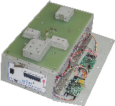
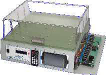
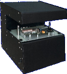
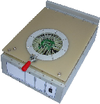
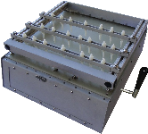
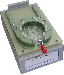
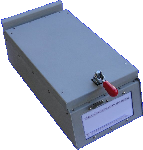
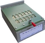
Bed of Nails Test Fixtures
Test Electronics

Click here to access our
Test Electronics ATE Software.


Enter
Login

Forgot Password?
Recover Password | Forgot your password? Recover it here.
Get Password Return
 
Register
Test Electronics

Testability

All White Papers

Follow as many of these specifications as possible as a guide to designing a circuit board that is the most cost effective and efficient to test. Not meeting all these specifications does not mean the board is untestable. It just means it may be a little more expensive to build the test fixture.

Testability
What is Testability?
Testability can best be described as the ease with which the functionality of any electronic product circuit or component can be determined to a desired degree of accuracy. To put it more simply, how easily can it be checked for performance to-spec throughout the entire product life cycle from product concept through design, manufacture, and service? How quickly can test programs be generated? How accessible are the test points? How comprehensive is the fault coverage?
Costs or Savings
Testability Pays Non-testability Costs / Testability Pays
Unpredictable production schedules, bonepiles of suspect boards, a very high cost of test, and an uncertain level of product quality delivered to the customer... these are the indirect costs of non-testability. Add the time spent trying to diagnose, and you quickly see that non-testability can be very expensive.

Testability, on the other hand, is introduced at the design stage, where it dramatically lowers the cost of test and the time spent at test. Properly managed, testability heightens your assurance of product quality and smoothes production scheduling.

Testability is not a technological innovation. It is a mindset that creates a constant awareness of the importance of ease-of-testing ... in engineering ... during production ... in the field. Testability is critical to the manufacturing process -- a product that cannot be readily tested is not really manufacturable.

The State of Combinational Test Technology. There are basically two approaches to test -- Functional Test and In-Circuit Test

Functional Test
Verifying the Entire Board.
Functional test is characterized by powering up the board and the application of input stimuli and measurement of the output signals on the circuit board. The measured output is compared against an expected result.
Functional test is aimed at verifying the functionality of the entire board. Functional test systems can be executed effectively at the speed of the design.
Functional test systems offer the potential of very high fault coverage and high confidence in the test results. However, functional test is based on two assumptions: the degree to which simulation technology can be applied to generating the test program, and the degree to which diagnostic strategies can be developed in a cost-effective and timely manner.
In-Circuit Test
Verifying the Components and the Assembly Process.
In-circuit test is characterized by not powering up the board, but applying stimuli and measurement of the signal nodes on the circuit board. In-circuit test is best described as testing the functionality of each component on the board, with the inference that the overall board functionality can be verified by the fact that each component functions and that it is wired properly.
In-circuit test generally does not execute at the speeds of the design, due to the fact that the physics of back-driving limits the technique's practicality to a range of between I and 10 MHz test speeds. Test access is assumed to be available at each node to support the effectiveness of this testing philosophy.

Combinational Test
In-circuit test has essentially moved in two different directions, namely:
The Manufacturing Defect Analyzer (MDA) is a highly simplified in-circuit tester that uses analog measurements to verify the manufacturing process. Primarily used on fairly simple circuit boards, the MDA is a low-priced test alternative that can provide good fault coverage for simple analog components and circuit interconnection. It provides no fault coverage for component functionality on digital, complex analog or mixed signal devices.
The Combinational Tester is currently the most popular method of board testing. This system combines the capability of an in-circuit tester with that of a functional test system to achieve very high fault coverage and excellent diagnostic accuracies. In addition to the high component coverage afforded by in-circuit analog and digital test techniques, the combinational tester supports analog, mixed-signal, and digital functional testing. It also supports the newer test and diagnostic concepts such as Boundary Scan, NAND Trees, and digital opens detection using analog means.
Combinational Testability.
design-for-testability
In order to design-for-testability, it is necessary to have a basic understanding of the capability of the combinational tester to provide test and diagnostics. This is best accomplished by examining the hardware, software, and fixturing technologies that support combinational test
Automatic Test Generation (ATG) has greatly enhanced the acceptance of combinational testing technology as a viable, cost-effective test approach. The ATG paradigm requires that information be available describing the components on the board (test models), their interconnects (circuit description), and their physical location (assembly).
Automatically capturing design information into the test generation process speeds test program development. The lack of the design data, on the other hand, can severely limit test effectiveness.


ATG Algorithms
Measure the Attributes of Each Component
ATG algorithms calculate the effect of the circuit on the ability to stimulate and to measure the attributes of each component In addition, ATG algorithms have to recognize the measurement accuracies and timing capabilities of the combinational tester hardware.
The capability of the tester to effectively isolate each component to accomplish the highest fault coverage test requires that analog "guard" and digital "inhibits and disables" be automatically entered into the program in order to minimize test development time.
The principal limitation to automatic test generation involves the lack of design data to create a test model for the devices on the board and to develop accurate fault coverage.
Content

Thank you for contacting Test Electronics.

Your responses will guide us in developing future products and
providing excellent customer support.

Please rate our service on the following aspects:

Service Excellent Very
good
Good Average Poor Didn't
notice
Products
Product Documentation
Technical Support
Applications Engineering
Website Content

What are your reasons for visiting our site today?

Product information Pricing information
Technical support information Other

What products are you currently in the market for?

What changes or additional products would you suggest?


Content

This is your Personal Notepad

Put notes in here as you browse our website for future reference.

Next Clear
Content

Get and Instant Product Price Quotation.

We hope to beat or meet your cost expectations.

Enter circuit board size:
Select Number of Sides to Probe:
Enter Number of Test Pins for each side:
BOT TOP BAK FNT LFT RGT
Leave unused sides blank

Press Plate Features:
Press Rods Edge Press Adjustable
BON Plate Features:
Standard QuickChange Adjustable
Durability:
50 Thousand 2 Million 10 Million
  50K Operations = 2 years at 100 tests/day 2M Operations = 8 years at 1000 tests/day 10M Operations = 10 years at 4000 tests/day

Additional Features:
Lever Latch Panel Inserts
Microcontroller Mid Carrier Plate
HV Shield RF Shield
Estimate Price and Availability
Enter carrier pallet size:
Select Base Material Type:
Pallet Material   Antistatic / Reflectivity:
No Carbon
White
HighCarbon
Black
Med Carbon
Grey
Material Thickness:
3mm 5mm
Hold Down Mechanism:
None SwivelLatch TensionPins
Durability Until Delamination:
12 Thousand 25 Thousand 50 Thousand
  12K Cycles = 6 months at 100 cycles/day 25K Cycles = 1 year at 100 cycles/day 50K Cycles = 2 years at 100 cycles/day

Pallet Material Durability:
Aluminum Stainless Titanium
Material Thickness:
0.0625inch 0.090inch 0.125inch
Hold Down Mechanism:
None SwivelLatch TensionPins

Additional Features:
Anodize Acid Etch
BeadPolish HeatTreat
Pallet Material   Conductivity:
No Carbon
NonConductive
Silicon Carbide
Semiconductive
Material Thickness:
2mm 3mm
Durability from Stress Pulveration Fractures:
1 Million 1.2 Million 2 Million
  1M Cycles Standard HS Machining 1.2M Cycles Bead Polished Finish 2M Cycles Polish & Heat Temper Treatment

Estimate Price and Availability

Submit